This is the first of a series of posts devoted to the (clever) usage of Arduino, with particular emphasis to scientific tasks. These posts are kindly sponsored by Farnell Element14 and are published under their site http://www.element14.com/community/groups/arduino. The content of these posts will also be available on my free publication on using Arduino for scientific purposes: Scientific Arduino.
With respect to other similar posts, mine will not only show how to do something using Arduino: as a physics teacher I will explain why you are required to do that. In order to use any tool at its best, it is important to understand how it works behind the scenes.
As a physicist I often do measurements. Some of them can be done using an Arduino board equipped with some sensor. In fact, the advent of Arduino boards was a great advantage, mostly for those in need of cheap data acquisition systems for scientific purposes, like teachers in high schools or graduate students.
Most scientists do not take measurements, analyse them and show results in one single application: taking data can be a hard job that can keep your CPU very busy. Hence, in most cases, they just take as much data as they can out of the sensors and barely copy them as such on some mass storage device. Those data are then analysed offline using the best available tools that not necessarily coincide with the best tools for data acquisition. Presentation is a further step: once data have been analysed, the relevant results must be presented in the proper way and that job can be done with an even different technology.
In this post we show how to use Arduino to take data from some sensor and store them for further analysis. There are at least two very effective solutions: storing data onto files on SD cards or transfer data over the Internet to a remote location. The first solution is fairly simple, but data cannot be accessed during data acquisition; if the data taking persists for a long time you may prefer adopting the second solution.
Let’s then assume we are going to use an Arduino board to get the values of few sensors during an experiment that lasts for a relatively long time. Moreover, imagine that the equipment used to take data needs to be kept in conditions such that it is difficult to have access to it (e.g. a dark room, or a climatic chamber). The only solution to get the data out of the system in almost real time is to use an Ethernet shield, i.e. an Arduino shield capable to connect to the Internet and exchange data over the connection.
In order for any device to connect to the Internet, the device must acquire a unique identity on the network: the IP address. The IP address (IP stands for Internet Protocol) of a device is a unique identifier composed, in the IPv4 version of the standard, the most commonly used, of four bytes, each of which can have a value between 0 and 255. Few of them are reserved internationally and, in particular, subnetworks whose first two bytes are 192 and 168 are non-routable, i.e. packets sent over such a network cannot go beyond an Internet switch. In other words they can only reach those devices on the same physical network. That’s why devices in a home network usually have IP addresses like 192.168.x.y. The IP address of a device can be statically or dynamically assigned to it. In the first case, the device administrator tells the device its IP address: in this case the address is going to remains the same with time forever. A device not having a static IP address can ask for an IP address to any computer on the same network running as a DHCP server (Dynamic Host Configuration Protocol). Depending on the configuration of the server, available IP addresses can be assigned to the device randomly or based on the device identity.
Every physical device, in fact, brings a unique MAC (Media Access Control) address: a set of six bytes, usually expressed in the hexadecimal notation, as 5e:a4:18:f0:8a:f6. The MAC address is broadcasted over the network so that a DHCP server can choose if the request must be ignored, served using a randomly chosen address or with a fixed address.
Having an IP address in not enough for a device to communicate with other devices: data packets must reach a special device, called the gateway, that knows how to send data to the recipient. The gateway, too, must be assigned an IP address and its address must be known to the devices aiming to communicate with others.
IP addresses can be associated to strings composed of a host name and a domain name. All devices on the same network shares the same domain name, while host names are unique. A DNS (Domain Name System) is a device able to associate the IP address of any other device to its host name.
The last piece of information needed to setup a network device is the subnet mask. This is a rather technical element, but we can think of it as a way to identify the range of addresses a device can reach directly through a gateway. It is usually in the form of an IP address (but it is not, it is a mask) and often equal to 255.255.255.0, meaning that all the devices on the same network share the first three bytes of their IP address.
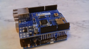
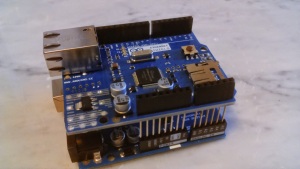
 We now have all the ingredients to connect our Arduino to the network: first of all plug the Ethernet shield to the Arduino board (see picture), then connect the shield to your router using an RJ45 cable. In order to configure the device you must know the MAC address of your shield (you can find it printed on the box or you can just invent it, provided it is unique in your network). Consider the following excerpt of Arduino sketch:
#include <Ethernet.h>
#include <SPI.h>

byte macAddr[] = {0x5e, 0xa4, 0x18, 0xf0, 0x8a, 0xf6};
IPAddress arduinoIP(192, 168, 1, 67);
IPAddress dnsIP(192, 168, 1, 254);
IPAddress gatewayIP(192, 168, 1, 254);
IPAddress subnetIP(255, 255, 255, 0);

void setup() {
  Ethernet.begin(mac, arduinoIP, dnsIP, gatewayIP, subnetIP);
}
Including Ethernet.h and SPI.h is mandatory: the files contain the definition of the classes used in the sketch. The MAC address is defined as an array of bytes, each of which is represented as a pair of hexadecimal digits (thanks to the 0x preceding each number). The IP addresses of the shield, the DNS and the gateway is given as an object of class IPAddress, as well as the subnet mask. The object constructor takes four arguments that represent the four bytes of the address. Our Arduino will acquire the IP address 192.168.1.67, in a network whose gateway’s address is 192.168.1.254; the gateway works also as the DNS in this case, while the subnetwork is restricted to those devices having an IP address like 192.168.1.x.
The Ethernet.begin(mac, arduinoIP, dnsIP, gatewayIP, subnetIP) call does the job: it configures the Ethernet shield as above (and, of course, it does that in the setup() method).
In many tutorials you can easily find a much simpler configuration, that reads as
#include <Ethernet.h>
#include <SPI.h>

byte mac[] = {0x5e, 0xa4, 0x18, 0xf0, 0x8a, 0xf6};

void setup() {
 Ethernet.begin(mac);
}
In this case the Ethernet shield acquire a dynamic IP address from a DHCP server on the network. In fact the begin() method of the Ethernet class exists in many variants (it is said to be polymorphic). To many novices the last sketch may appear much more convenient: it’s simpler and shorter and does not require the knowledge of too much parameters. However, the length of the source code has mostly nothing to do with the size of the sketch in the Arduino memory.
This happens because what is stored in the Arduino memory is not the sketch as you can see here, but the sketch in machine language. Microprocessors work using electrical signals representing data and instructions. Because an electrical device can be easily found in two states (e.g. on/off), information (data and instructions) is represented as binary strings. A program for a microprocessor is then a long sequence of bits 0 and 1, not a flow of characters. The characters you write in the editor are translated into corresponding sequences of bits by the compiler (automatically invoked before uploading the sketch or when you click on the Verify button of the Arduino IDE). It is this long sequence of bits that is uploaded on the Arduino memory, not your sketch.
It happens that, in order for the shield to ask for an IP address to a DHCP server, the number of operations to perform is much larger with respect to those needed to assign manually all the parameters. As a result, the compiled program in the two cases is very different in size: the first sketch takes 2634 bytes in memory, once added an empty loop() method; the latter takes 10424 bytes! It’s about a factor 4 more space!
The memory space of an Arduino is precious, since it is not so large: as a result you may prefer the apparently longer sketch of the first example to the second one.
Now we own an Internet connected Arduino board. We are going to take data with it and send them to some remote storage for further analysis. In the next post we will show how to do that efficiently. Stay tuned…


Condividerò il post con i miei followers di Twitter
"Mi piace""Mi piace"